
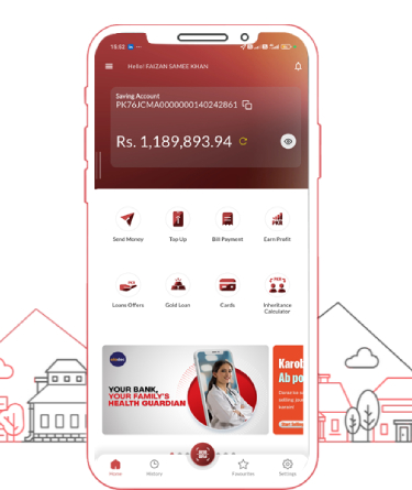
DOST App
A schematic for this board would be essential for:
When a motherboard fails to post or show signs of life, a technician follows the schematic to check the standard Intel power-up sequence. The H-IG41-uATX relies on specific voltage regulators to convert 12V and 5V rails from the 24-pin ATX connector into usable power. 1. Always-On Standby Voltage (+5V_SB & +3.3V_ALW) h-ig41-uatx rev 1.1 schematic
У H-IG41-uATX Rev 1.1 есть несколько уязвимостей, которые часто являются причиной поиска схемы: A schematic for this board would be essential
Do not just search for the marketing name. Look at the physical motherboard for silk-screened manufacturer codes such as Eton ET856 or Foxconn internal model numbers (e.g., Foxconn G41 series variants). Always-On Standby Voltage (+5V_SB & +3
Beyond component interconnect, the schematic encodes the board’s behavior. ensures that 3.3V standby is stable before enabling the main 12V rails. A small microcontroller or discrete logic gates (74xx series) manages the front-panel power button, generating the PS_ON# signal to the ATX power supply.
DOST application hosts a wide array of features, which are available to MMBL customers 24/7. It offers real-time access to all your account information. Key features include:
* Login/Self-Registration (Account-Based)
* Link/Delink Account.
* Account Summary
* Account Statement
* Customer Profile Management
* Demographics Update
* Money Transfer To MMBL
* Money Transfer Other Bank Accounts
* Loan Application
* Term Deposit
* Utility Bill Payment
* Mobile Top-up
* Purchasing
* Favorites Management
* Request for Instrument
* Block Cheque (Single, Series)
* Loan Summary
* Debit Card Management
* PIN Changing
* Temporary Card Blocking
* Card Unblocking
* Permanent Card Blocking
* Complaint Registration
* Branch & ATM Locator
* Password Changing/Reset